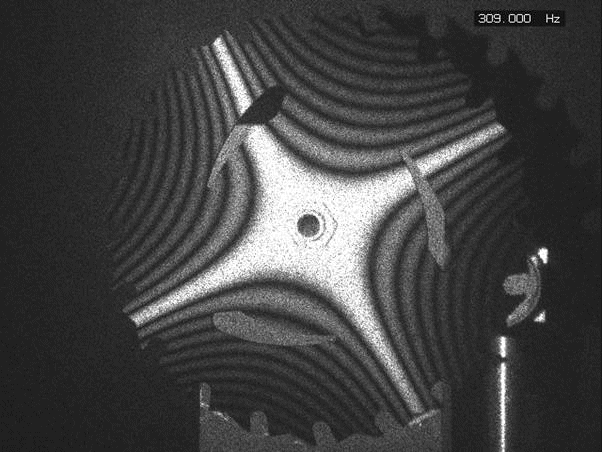
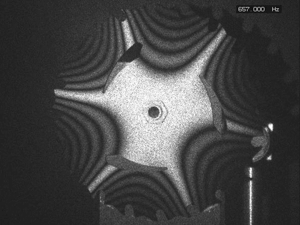
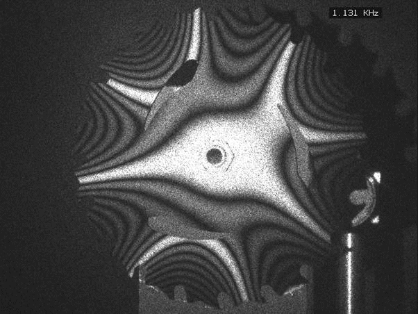
The Problem: To Identify and Characterize Vibration Modes
The
K100/HOL optical head using the HoloFringe300 interferometry program
allows quick identification of vibration modes of a test structure as it
is subjected to a vibratory excitation. The vibration modes show up as
Bessel function fringes. These fringes are dark bands on the image that
read like a topographical map showing the peaks and valleys of the
vibration amplitude. The program controls a dual frequency generator via
the PC host computer to provide excitation.
The second signal can be used to produce wrapped phase fringes,
which are easily converted to numerical data.
No scanning of the object is required, resonant frequencies are
easily located, and resonant bandwidths can also be obtained.
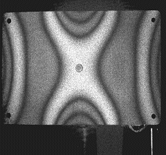
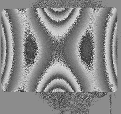
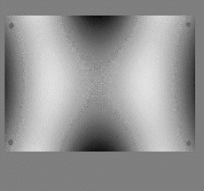
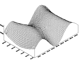
Vibration Mode Analysis of a Rectangular Plate. The upper left image shows the vibration mode of the plate as a set of zero-order Bessel function fringes. This is what the system displays in real-time for mode identification. Upper right shows that fringe pattern converted to the wrapped phase function. Lower left shows the unwrapped phase function, otherwise known as the fringe locus function. Lower right shows a 3D plot of the vibration mode. Note that the plate has four holes in it that present no problem to the unwrapping program.
![]()
ABSTRACT: A simple modification is
described to allow capture of digital holograms with two separated
illuminations of a vibrating object using a standard digital holography
system. The object is a small wine glass vibrating in a two-diameter mode
and a three-diameter mode. Image data is resolved into axial and
transverse components, and horizontal data scans are resolved into
magnitude and angular direction.
