The Problem: To Measure Static Deformations
The
K100/HOL optical head using the HoloFringe300 interferometry program
allows identification in real-time of the deformations of a test
structure subject to a static load. The deformations show up as
cosine fringes. These fringes appear as dark bands on the object that
connects points of common deformation. The system can also display
phase-image fringes. These fringes are the wrapped phase of the cosine
fringe function, and relate directly to the object deformation. A
robust phase-unwrap program converts the wrapped phase fringes to
numerical data for comparison with finite element analyses models.
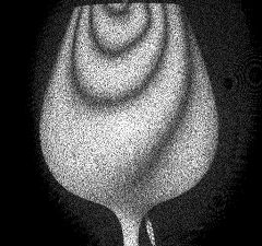
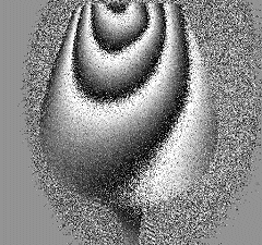
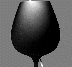
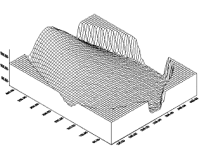
Deformation Analysis of a Wine Goblet. The upper left image shows the real-time fringes of the goblet's deformation due to a rod placed inside it and leaning on the rim. Upper right shows the same deformation displayed in real-time as wrapped phase fringes. Note the fringes have an asymmetrical saw-tooth form. The lower left image shows the unwrapped phase fringes, or fringe locus function. Lower right shows the goblet deformation as a 3D plot.
![]()
ABSTRACT: A method is presented for measuring vibratory strain fields using phase-stepped, image-plane digital holography.
An object surface is observed along its normal vector while illuminated at equal and opposite angles by two
mutually coherent laser beams. One beam is phase stepped by quarter-wavelength
increments between TV frames, and the resulting images are processed to yield holographic images.
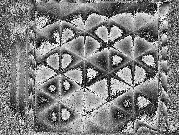
Thermal
Deformation of a carbon/epoxy structure
Unwrapped
deformation image of the structure shown above.
