The Time Average Vibration Data Routine and Phase Unwrap
Step 1. The program first records an image of the object, without vibration, to serve as a mask during phase unwrapping. It is usually assumed that image points below a certain threshold will lie outside the object and above it will lie within the object, but the mask can be edited to eliminate points that are ambiguous or troublesome, or to draw a mask covering the object. The phase unwrap routine thresholds the mask and applies erosion and dilation. This image is provided for use in the ModeMatch program.
Step 2. The program then displays a standard time-average hologram, in real-time, which the user can observe to locate the vibration mode and identify its frequency of maximum response. The user is instructed to adjust the amplitude until no more than the fifth zero of the J0 function is displayed, because beyond that level the amplitude of J02 function may be too low to provide accurate data.
Step 3. The program switches control to the bias vibration generator and the user is instructed to increase its amplitude until the zero-order fringe disappears and then to adjust its phase until it returns with maximum brightness. The range over which the zero-order fringe can be seen is actually quite broad, so the program guides the user to find phase values below and above this point where the zero-order fringe appears equal in brightness to its neighbors, and then it take the average of those values.
Step 4. The excitation to the object is turned off and the user is instructed to increase the bias amplitude until the image appears as black as possible. This corresponds to the first zero of the J0 function at an argument value of 2.4048. The program captures that value upon transition to the next step.
Step 5. The program then proceeds to capture an image of the vibrating object without bias vibration and asks the user to mark a point on the zero-order fringe. This point is used to tell the unwrapping program where the unwrapped phase function should be approximately zero.
Step 6. After this point is marked, the program then captures four interferograms at bias levels corresponding to an equivalent phase shift of 135°, 45°, -45°, and -135° relative to the periodicity of the J02 function. The interferograms are processed by the standard four-step algorithm and the wrapped phase function is displayed. In addition, a set of images is created from this data for use in phase unwrapping.
Step 7. The program instructs the user to save this data set for unwrapping by a program based on calculated unwrap regions.2 The phase unwrap program first adds multiples of 2 pi to the values of the wrapped phase function in order to obtain a smooth phase function. The entire unwrapped phase function is then shifted by a multiple of 2 pi so that the values around the point that was marked as lying on the zero-order fringe are as close to zero as possible. The unwrapped phase function is then read through a look-up table that corrects for the fact that the J0 function is not actually a cosine function. The final data is stored in two files, a *.out file that contains sixteen bit pixels where values of 256 corresponds to one cycle of phase, and a *.img file that has eight bit pixels scaled so that the minimum value is 0 and the maximum value is 255. This latter file is used to display the resulting phase function.
Modal
Assurance Criteria and Holographic Vibration Analysis
Modal Assurance Criteria (MAC) are commonly used to quantify the similarity of vibration mode patterns on similar but different objects. Let us designate two similar vibration patterns for two separate structures as Y1 and Y2. In general these will be vectorial quantities, but for holography with a single perspective, they will be scalars. The MAC calculation for these two patterns is
MAC = [SY1 Y2]2/[SY12 SY22], (1)
where S indicates a summation over the number of data points on the object. Note that this calculation is self-normalizing and any factor multiplying either pattern will be canceled allowing the MAC values range from 0 to 1. In order to apply this calculation to holographic vibration analysis data, several things must be considered. First, the images of both objects should be the same size in the data file. This can be accomplished by locating both objects the same distance from the holographic optical head so as to eliminate size variation. The K100/HOL optical head uses a zoom lens to provide images of the objects under study, and it is essential, therefore, that the zoom lens magnification remain constant throughout such tests. It is also necessary that the two objects exhibit no relative rotation. Small shifts in vertical or horizontal position may be accounted for by software analysis. The same image file that is used for guiding the phase unwrap program is provided as a mask to define the valid pixels on the object for the MAC calculations.
Illustrative
Experiment
A flat aluminum plate, 153 mm long by 38 mm wide, by 3 mm thick, was chosen to approximate the shape of a blade and it was clamped at one end for a length of 24 mm to simulate the mounting of a bladed disk. The clamping vise was cemented to a translation stage so that misregistration could be simulated. The plate was modified by fixing a weight to either of the free corners. The use of two weights, 0.15 g and 0.7 g, placed in either of the two positions allowed simulation of four departures from the modal structure of the unperturbed plate. The weight of the entire plate, including the clamped section, was 47.7 g.
Figures 1 through 5 show the five vibration modes recorded as J0 fringes for the five conditions of the plate, which have been designated as different blades, i.e., blades 1, 2, 3, 4, and 5. The images have been organized to show mode 1 for blades 1 through 5 in one column, mode 2 for blades 1 through 5 in the next column, etc. This allows comparison of how the modes have changed with the perturbation. Figures 6a through 6e show images of the data for the fifth modes of blades 1 through 5, and they located to the right of their corresponding J0 images.
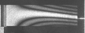
Fig. 1 Blade 1 Mode 3 – 998 Hz
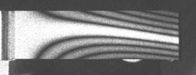
Fig. 2 Blade 2 Mode 3 - 983 Hz
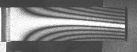
Fig. 3 Blade 3 Mode 3 – 980 Hz
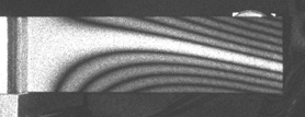
Fig. 4 Blade 4 Mode 3 – 956 Hz
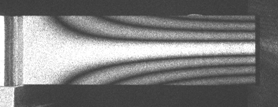
Fig. 5 Blade 5 Mode 3 – 974 Hz

Fig. 6a Data Image of Blade 1 Mode 5

Fig. 6b Data Image of Blade 2 Mode 5

Fig. 6c Data Image of Blade 3 Mode 5

Fig. 6d Data Image of Blade 4 Mode 5

Fig. 6e Data Image of Blade 5 Mode 5
An auxiliary program is provided to perform MAC calculations
using the data in the *.out files.
In order for the program to work efficiently, the data must be
organized as follows: 1 overall folder for the entire test with
separate folders within it for each blade tested.
A standard blade is specified and its mask.
The program will then identify all blade modes within the
subfolders of the test folder and use the *.out files to calculate MAC
values. The output is
provided as a table that may be saved as a comma separated value file
that can be read by a spread sheet program.
Table 1 shows the MAC values for the modes above.
|
|
Blade 1 |
Blade 2 |
Blade 3 |
Blade 4 |
Blade 5 |
|
Mode 1 |
1.0 |
0.998 |
0.998 |
0.998 |
0.998 |
|
Mode 2 |
1.0 |
0.992 |
0.995 |
0.957 |
0.953 |
|
Mode 3 |
1.0 |
0.982 |
0.984 |
0.949 |
0.925 |
|
Mode 4 |
1.0 |
0.994 |
0.994 |
0.981 |
0.986 |
|
Mode 5 |
1.0 |
0.993 |
0.988 |
0.967 |
0.969 |
It can be seen that mode 1 was not perturbed much at all by the addition of the weights, and the most change occurred with modes 2 and 3 of blades 4 and 5.
1. Stetson K. A., Brohinsky W. R (1988) A Fringe Shifting Technique for Numerical Analysis of Time-Average Holograms of Vibrating Objects, J. Opt. Soc. Amer. A 5:1472-1476.
2. Stetson K. A., Wahid J., Gauthier P., (1997) Noise-immune phase unwrapping by use of calculated wrap regions, Appl. Opt. 36:4830-4838 (1997).